
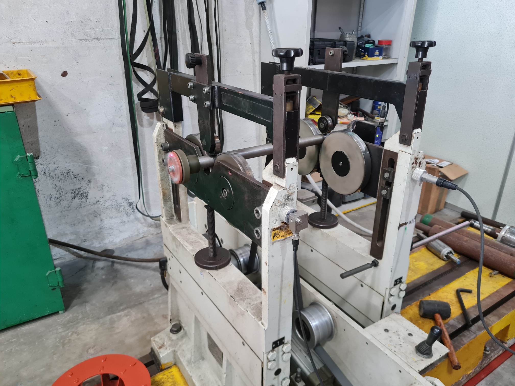
Shaft balancing can refer to a bare shaft or to a shaft carrying pulleys, hubs, impellers, couplings or other rotating fitments. The first requirement is to define exactly what is being balanced. A good result on one assembly condition may not transfer perfectly to another if components are removed, rotated, keyed differently or fitted with eccentricity.
Typical shaft work
- Bare rigid shafts where balance verification is required
- Shaft-and-pulley assemblies
- Shafts with hubs, spacers or couplings
- Repaired or machined shaft assemblies
- Rotor shafts prepared for later component assembly
Common problems mistaken for shaft unbalance
Bend, journal runout, eccentric fits, damaged centres, fretting, worn bearing seats and misaligned assembled components can all produce vibration or poor repeatability. A balancing machine can measure the unbalance of the mounted condition, but adding weight is not a substitute for correcting unacceptable geometry.
Rotor size capability
| Parameter | Current declared capability |
|---|---|
| Rotor weight | Below 800 kg |
| Maximum diameter | 1.3 m |
| Rotor length | 400 mm to 2.5 m |
For shafts, journal spacing, shaft stiffness, support location and the mass distribution of fitted components usually govern setup suitability.
Single-plane vs two-plane balancing
A shaft assembly generally has axial length and can carry couple unbalance, so two-plane balancing is often appropriate. One-plane correction may be used for a dominant disc-like component in a suitable configuration, but it should not be assumed simply because the measured amplitude looks small in one support.
Correction methods
Correction can involve approved material removal, addition or relocation of balance mass on designated features, or correction on fitted components. The method must respect stress concentration, minimum wall or flange thickness, keyways, threads, fits and other functional surfaces.
Balancing a shaft with a keyway
The key condition matters. A shaft balanced with a full key, no key or an incorrectly represented key can transfer an artificial unbalance into the final assembly. ISO 21940-32 specifies a half-key convention for separately balanced keyed components. The report should state the convention or actual assembly condition used.
What the customer should provide
- Shaft drawing or main dimensions
- Journal diameters and support locations
- Known runout or straightness readings
- Operating speed
- List of fitted rotating components and whether they remain installed
- Keyway and key condition
- Recent repair, metal spray, sleeving, welding or machining history
- Required balance grade or OEM tolerance
Balancing report
The report can record the shaft assembly condition, key condition, correction planes, initial measurements, correction and final residual unbalance. This assembly information is important when the shaft is later dismantled or components are replaced.
Subang Jaya workshop
RDB’s workshop in Subang Jaya accepts industrial shafts and shaft assemblies subject to geometry and safe setup review. Send the shaft drawing or clear dimensioned photographs before delivery for unusual configurations.
See also Balancing a rotor with a keyway and Static balancing vs dynamic balancing.