
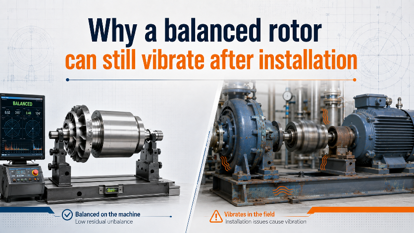
Balancing reduces one specific vibration source: force and moment caused by residual mass unbalance. It does not certify that the complete machine will have low vibration after installation.
The balancing machine and the installed machine are different systems
In the balancing machine, the rotor is supported, driven and measured under a controlled setup. The aim is to estimate residual unbalance and apply correction. In service, the rotor is installed with its actual bearings, coupling, casing, foundation, aerodynamic or hydraulic load and structural resonances. Those conditions can create vibration even when rotor unbalance is low.
1. Assembly eccentricity or poor mounting repeatability
A rotor may be balanced about one rotational axis and then run about a slightly different axis after installation. Causes include loose fits, damaged registers, taper seating errors, bore clearance, dirt between mating faces, incorrect key condition and component repositioning. A small radial shift can create a new unbalance proportional to rotor mass.
2. Bent shaft or excessive runout
A bent shaft is not simply an unbalanced shaft. Adding correction mass can reduce a measured 1× response in one condition, but the geometric error remains. Runout can also change clearances, seal forces and bearing loading.
3. Misalignment
Coupling misalignment can create strong running-speed vibration and harmonics. The exact pattern depends on coupling type, machine stiffness and measurement direction, so 1× vibration alone should not be treated as proof of unbalance.
4. Structural resonance
Unbalance force increases with the square of rotational speed, but the machine’s vibration amplitude also depends strongly on dynamic stiffness. If running speed is near a structural natural frequency, a modest forcing level can produce a large vibration response. The same rotor can therefore look acceptable in one support system and severe in another.
5. Bearing condition, looseness or soft support
Damaged bearings, incorrect clearances, loose bearing housings, cracked structures, soft foot and foundation flexibility can amplify or generate vibration. Balancing cannot restore mechanical stiffness or bearing geometry.
6. Aerodynamic or hydraulic forces
Fans, pumps and impellers operate in a fluid field. Blade-pass excitation, turbulence, recirculation, cavitation, uneven inlet conditions and process build-up can produce vibration that does not exist on the balancing machine.
7. Rotor condition changes after balancing
Loose deposits, water retention, coating, product build-up, moving internal material, detachable balance weights, blade damage or later repair can change the balance state. The rotor may have been balanced correctly at the time and then physically changed.
8. Flexible rotor behaviour
A rotor that behaves rigidly at low balancing speed may develop significant elastic deflection near or above a critical speed. Rigid-rotor balancing procedures do not automatically solve flexible-rotor response. ISO 21940 treats rigid and flexible rotor procedures separately.
How to investigate logically
- Verify that the rotor was installed in the same assembly and key condition used for balancing.
- Measure shaft and fit runout.
- Check alignment, bearing condition, hold-downs and foundation stiffness.
- Compare vibration amplitude and phase at 1× RPM across bearings and directions.
- Review whether the vibration changes with speed, load, flow or temperature.
- Look for harmonics, blade-pass components and broadband energy rather than focusing only on overall RMS.
A “balanced rotor” means residual unbalance was reduced under a stated setup and acceptance basis. It is not a certificate that every installed vibration source has been eliminated.
Related services: fan rotor balancing and impeller balancing.